Before, we were streaming raw RGB values that were either randomly generated or monotonically increasing sequence. But as the purpose is to stream HDMI traffic, it makes sense to capture some real HDMI traffic and stream it through the packetizer. The last blog was an effort in this direction. We also have added HSYNC and VSYNC signals to the interface. See Figure 6 of the Specification.
Now we can't just stream RGB values through the packetizer interface. Now we need to conform to HDMI protocol, which means we either assert HSYNC and VSYNC according to the protocol or somehow capture the traffic that already has this information. This is where the last blog comes into the picture. I was successfully able to generate HDMI traffic and dump it into a file. Packetizer then reads this file and sends the data downstream accordingly. The files are here.
More later!!!
Monday, June 30, 2014
Monday, June 23, 2014
Implementing XAPP 495 on Spartan 6
Today, i decided to do hardware testing and chose to implement the VTC reference design given in http://bit.ly/1lluJn1 on Atlys board. I was able to implement the design successfully on Atlys board.
Here are a few snapshots of the 720p frame


HSync and VSync signals shall also be added to the packetizer upstream interface.
Here are a few snapshots of the 720p frame
Not only that, i was able to capture this HDMI traffic for the purpose of using it as RTP payload. I shall add the Verilog files that capture the HDMI to the bitbucket tomorrow. Here is a snapshot of the captured HDMI traffic going from FPGA to the monitor.
720p resolution chosen
512: en=1,hsync=1,vsync=1,red= 0,green= 0,blue= 0
525: en=1,hsync=0,vsync=0,red= 0,green= 0,blue= 0
539: en=1,hsync=0,vsync=0,red= 0,green= 0,blue= 0
553: en=1,hsync=0,vsync=0,red= 0,green= 0,blue= 0
566: en=1,hsync=0,vsync=0,red= 0,green= 0,blue= 0
580: en=1,hsync=0,vsync=0,red= 0,green= 0,blue= 0
593: en=1,hsync=0,vsync=0,red= 0,green= 0,blue= 0
607: en=1,hsync=0,vsync=0,red= 0,green= 0,blue= 0
620: en=1,hsync=0,vsync=0,red= 0,green= 0,blue= 0
634: en=1,hsync=0,vsync=0,red= 0,green= 0,blue= 0
647: en=1,hsync=0,vsync=0,red= 0,green= 0,blue= 0
661: en=1,hsync=0,vsync=0,red= 0,green= 0,blue= 0
.
.
.
Friday, June 20, 2014
Downstream interface of RTP Verilog core
Today, i wanted to finish downstream interface of the RTP Verilog core. See Figure 6 of the Spec to see how the downstream interface looks like. The downstream block is the MAC (Media Access Controller). At the moment, the idea is to send RTP packets to the MAC. Once this is working, we can then insert UDP/IP/Ethernet headers and send it to the downstream interface as a realistic packet.
I got the downstream interface working but it is lagging. What this means is that packet arrival is faster than packet departure. There are two ways to deal with this. One is to back-pressure the upstream interface until the packet is sent downstream. This means you cannot get new data from upstream interface until all the previous data has drained downstream. The other approach is to use a reasonably sized FIFO and let the arrived data fill up the FIFO. While new data arrives at the FIFO, downstream block consumes data from FIFO.
Initially, i am going to try the first approach. Later, i can deal with the second approach.
What i first encountered during synthesis was of course
Synthesis Errors !!!!
ERROR:HDLCompiler:1401 - "/home/user/gsoc14/python_code/myhdl_code/sim_models/rtp_xilinx/rtl/packetizer.v" Line 148: Signal nxt_fifo_full in unit packetizer is connected to following multiple drivers:
Driver 0: output signal nxt_fifo_full of instance Latch (nxt_fifo_full).
Driver 1: output signal nxt_fifo_full of instance Multiplexer (fifo_full_fifo_full_MUX_20689).
ERROR:HDLCompiler:1401 - "/home/user/gsoc14/python_code/myhdl_code/sim_models/rtp_xilinx/rtl/packetizer.v" Line 220: Signal nxt_send_buffer[10399] in unit packetizer is connected to following multiple drivers:
So i had to rewrite RTL to make these Errors go away. I was able to do rewrite RTL as well as synthesize correctly. Here is the synthesis log file. Here is the synthesized netlist and testbench
Please run the code and help me find bugs that you come across.
Here is the output for a few clock cycles. The format is timestamp : 4bytes of RTP Data
4356:80180000
4376:00000000
4416:00000501
4436:001a0000
4456:00010000
4476:02000003
4496:00000400
4516:00050000
4536:06000007
4556:00000800
4576:00090000
4596:0a00000b
.
.
.
I will do more testing next week.
Thursday, June 19, 2014
Testing and expansion of RTP Verilog model continues ...
The RTP Verilog RTL is complete and now it sends full 1280 pixel line (1280 x 3 bytes) as three packets of size 1281 bytes, 1281 bytes and 1278 bytes. See the revised Specification (in particular page 2). The difference from yesterday is the amount of data and testing. Yesterday it was tested with toy data. Today it is tested with data that is close to real life i.e., full 1280 pixel lines
The RTP Verilog RTL is uploaded to bitbucket. The design has also gone through synthesis and post-synthesis simulation Link. If you run post-synthesis simulation, you may not observe anything at the output. The reason is that pkt_data is no longer an output port. This is because
1) It was added for observability and debugging purposes. It is not part of upstream or downstream interfaces
2) Its size is huge i.e., 1300 bytes i.e., reg [1300*8-1:0] pkt_data . Xilinx Spartan6 FPGA does not have these many pins to allocate.
For above reasons, pkt_data is kept as an internal signal for synthesis. But this is not the case in RTL, where pkt_data signal is available as an output port so you may see full pkt_data as shown below. I am showing one packet (i.e. first 1281 bytes of the first pixel line). 4136 is the time stamp in nanoseconds
4316: 80180000000000000000000000000501001a0000000000000100000200000300000400000500000600000700000800000900000a00000b00000c00000d00000e00000f00001000001100001200001300001400001500001600001700001800001900001a00001b00001c00001d00001e00001f00002000002100002200002300002400002500002600002700002800002900002a00002b00002c00002d00002e00002f00003000003100003200003300003400003500003600003700003800003900003a00003b00003c00003d00003e00003f00004000004100004200004300004400004500004600004700004800004900004a00004b00004c00004d00004e00004f00005000005100005200005300005400005500005600005700005800005900005a00005b00005c00005d00005e00005f00006000006100006200006300006400006500006600006700006800006900006a00006b00006c00006d00006e00006f00007000007100007200007300007400007500007600007700007800007900007a00007b00007c00007d00007e00007f00008000008100008200008300008400008500008600008700008800008900008a00008b00008c00008d00008e00008f00009000009100009200009300009400009500009600009700009800009900009a00009b00009c00009d00009e00009f0000a00000a10000a20000a30000a40000a50000a60000a70000a80000a90000aa0000ab0000ac0000ad0000ae0000af0000b00000b10000b20000b30000b40000b50000b60000b70000b80000b90000ba0000bb0000bc0000bd0000be0000bf0000c00000c10000c20000c30000c40000c50000c60000c70000c80000c90000ca0000cb0000cc0000cd0000ce0000cf0000d00000d10000d20000d30000d40000d50000d60000d70000d80000d90000da0000db0000dc0000dd0000de0000df0000e00000e10000e20000e30000e40000e50000e60000e70000e80000e90000ea0000eb0000ec0000ed0000ee0000ef0000f00000f10000f20000f30000f40000f50000f60000f70000f80000f90000fa0000fb0000fc0000fd0000fe0000ff00010000010100010200010300010400010500010600010700010800010900010a00010b00010c00010d00010e00010f00011000011100011200011300011400011500011600011700011800011900011a00011b00011c00011d00011e00011f00012000012100012200012300012400012500012600012700012800012900012a00012b00012c00012d00012e00012f00013000013100013200013300013400013500013600013700013800013900013a00013b00013c00013d00013e00013f00014000014100014200014300014400014500014600014700014800014900014a00014b00014c00014d00014e00014f00015000015100015200015300015400015500015600015700015800015900015a00015b00015c00015d00015e00015f00016000016100016200016300016400016500016600016700016800016900016a00016b00016c00016d00016e00016f00017000017100017200017300017400017500017600017700017800017900017a00017b00017c00017d00017e00017f00018000018100018200018300018400018500018600018700018800018900018a00018b00018c00018d00018e00018f00019000019100019200019300019400019500019600019700019800019900019a00019b00019c00019d00019e00019f0001a00001a10001a20001a30001a40001a50001a60001a70001a80001a90001aa
The last RGB value is 0x01aa which translates to 426. Since the payload started from 0, there are 427 pixel values (427x3 = 1281 bytes) have been packetized as RTP payload. I kept the RGB data as monotonically increasing integers starting from 0 to simplify testing and debugging. The design does not drop a single RGB data across packet boundaries. I have myself verified this. If you can find bugs in this code, please bring them to my attention by submitting a pull request or commenting below.
Time permitting, i will look at MyHDL stuff as Chris has put a lot of stuff. See yaa
RTP Verilog Code and Synthesis
Today was getting hands dirty writing Verilog code. The interface of the RTP core is shown in Figure 6 of Specification. Note that RTP core will add UDP/IP and Ethernet Headers as well in the near future. The code correctly generates RTP packet i.e., header and payload (chosen to be small enough to debug).The design has also gone through synthesis Xilinx Synthesis flow and successfully post-synthesis simulation. The code is available on bitbucket. The RTL file for RTP is packetizer.v, the testbench is tb_packetizer.v. The post-synthesis netlist is packetizer_synthesis.v. You need Xilinx unisims, simprims, uni9000 and unimacro libraries to run the post-synthesis simulation.
Here is a brief log of the RTL Run. If you have read the Specification (in particular pages 3-4), this should make sense
0: 0000000000000000000000000000000000000000000000000000000000
145: 80180000000000000000000000000500001a0000000007000008000009
195: 80180001000000000000000000000500001a050000000a00000b00000c
245: 80180002000000000000000000000500001a0a0000000d00000e00000f
295: 80180003000000000000000000000500001b0000000010000011000012
345: 80180004000000000000000000000500001b0500000013000014000015
395: 80180005000000000000000000000500001b0a00000016000017000018
445: 80180006000000000000000000000500001c000000001900001a00001b
495: 80180007000000000000000000000500001c050000001c00001d00001e
Here is a snapshot of the RTL simulation
Here is a brief log of the post-synthesis simulation
0: 0000000000000000000000000000000000000000000000000000000000
145: 80180000000000000000000000000500001a0000000007000008000009
195: 80180001000000000000000000000500001a050000000a00000b00000c
245: 80180002000000000000000000000500001a0a0000000d00000e00000f
295: 80180003000000000000000000000500001b0000000010000011000012
345: 80180004000000000000000000000500001b0500000013000014000015
395: 80180005000000000000000000000500001b0a00000016000017000018
445: 80180006000000000000000000000500001c000000001900001a00001b
495: 80180007000000000000000000000500001c050000001c00001d00001e
545: 80180008000000000000000000000500001c0a0000001f000020000021
595: 80180009000000000000000000000500001d0000000022000023000024
Here is a snapshot of the post-synthesis simulation
The Synthesis summary report is packetizer.syr
As the code is uploaded to bitbucket, please help test it. Thanks in advance
Tuesday, June 17, 2014
Documentation and Looking at UDP core
Part of good working habit is to document every thing. I have seen it and i believe it is extremely useful. So read the Spec
As i am done with RTP golden model, i am about to write RTP Verilog model. I was figuring out myself as well as with my mentor what would the interface to UDP core look like.There are two possibilities
1)Assume there is downstream UDP core to begin with that accepts data.In this case, interface is easy as you can see how UDP accepts data.
2) If no UDP core or UDP core does not have interface to accept data, then you can add UDP header on the same spot where you are inserting RTP header. Not only that, you can also insert IP header as well. That means now you have to interface RTP with the MAC core.
The two cores i looked at are
http://www.joelw.id.au/FPGA/DigilentAtlysResources
This falls in the 2nd category
and
http://opencores.org/project,udp_ip_stack
which is sadly down throughout today and i could n't figure out if it belongs to 1st of 2nd category. I will try again tomorrow.
Monday, June 16, 2014
RTP packetizer golden model
A working RTP packetizer has been developed to deal with uncompressed RTP payload. It is working after some basic testing. Here is the code.You need modified rtp.py which is also included in the code. Tomorrow i shall add the documentation to tell you how i did all this and why i did it that way?
Monday, June 2, 2014
RTP packet creation in Python from raw video stream
OK finally got the basic RTP packet creation done in Python using MyHDL and Dpkt libraries
Please look at the source code here. Note that you need to have MyHDL and Dpkt libraries installed to get this code to run.


Here is the RTP packet of length 1086 bytes. Only the RTP payload is shown.
raw_bytes=ACE19577A2EB3665189599C2644D56420366CE5D386E802AFD79E54852C9C2AAB8C6DE15974BCEC18F7B7D3D0C8D50ED37D7808D498F4D773FF5D29278EC24BE1572F68F56BC2AF94E544148563E9493F585E2E9C3FBE7DA38D520656158D794D8F06D926B8B7B3B49B60974B7A0E1DC3496B1DAD4F110220366C35AD6217AC0EFC15FB2734DBD0D1D60B27E3FFAF13A2344BA3E8B2CF7276BFB1C94E2F86A9C503DF79F2882C948A8EE8572D7B09CE197D1F95E62285FB918009F25C41B4CA405AC51A28B3C71A6D28F450E64CD7A6DD7BB6CD48FE2035FE5BF30A16C3E67287C2BF9A1213FBE5EF98CA58BA22DA618B716AC98E4618EE450CB62CF57C0D4C626A652B9D47A539CF568641A7EBB750899DB81CBD3D09CC121ED2E48A8429FF72C214F88C028ABB2BE8FD6DFB79E36D0E8A42EA09B472AA3B82177DABD182B9938010688782C6663B9B515DEF5072A518640D7486723297E017A4C2C94F3E781E510B95BD0A74B51584AC39F477585BA4F70ED625F2D6477C5B1357D3C36EFAD68165D97AC3E1216A8E6B96EB6F2FB30562D24CEF996E1C675DEA2E5D977F3C0A1C3103ED7E2774CE69C1F136D5043CC9E4AA6E78A05D3113798AA0439C131EC4CCD509375EBC9942A67B44E8DC1DC992AEE7D56E0733716327E16831D8DE0453740C5A250B6352F4F74C411911DE4714D3ACCC6C71D4D614B68ACA6B676A97533604A491AE262D1AAC6AF55A45BEC0AEA382262F6036A8CBE0471FE3AB7AD7ACE1ED565D715E9B6CE0308FB019B7661E68FBB13512F6413AC5EC5456D83863BEEC1A53D9DDF857FC36D1EB732D07FECE2430B10FE253A60953AFCB38790899C775844F422DB83B5AB2A12443711BF46BA5C35E1C2BAD4BCC464ED59A4D924993A295006B34B63693E7B6A414D5894F91985E58AEEAAA08C430F7C354CBDCF43BD3D5458DC1856458919E001CFCA45BD12536F2B9D6855622741C58D7359C17F8AA943A147E36E634BA89E9EDD92188F3CE4E72DA2AF8D2B267248A9FCAA5C30D141DF2548FCE7531414D106AE4EEA84887984700F09C3A8D9E67B614CB7A1B417233D1D97EFC13F30011BE67EEE5CDACCD933816046E7919E2D22C568614756AE3E26323FCBE892968F2D99B655A18A4961A3C0F0DFE4FC56442071FD9516765998287E507CA9C58FDB2E8281CBF1B11942C919B36102A2B55AC9544094A6B78A931687552AC48BD9D4C0D580271A9FE19D37787959428DF04C886E38A39F2C601B9A299D70C4F6B4E82D7A02C8DD72B5F7A73596A29E13E4D6BE0F183C86E2CCDB6A95FC06AAF58754A21F6ABC3EC8237CACDCB55DE06D9651EF2E6A230E12C1BBB378B23CD785668DEEEDF06E8A2F71A0D6166B1BD281D729CDF2AC9763F0FDD390DB7025637EF68C6AD40AF1B01CB52A5BA289782B299C35550D6B5F0A4B6931F42226F455448403A77A29FA746C5CC27CFC81808E77A5DBCCC6D9BE5CB5E892A1CF2429FFC5EE8DE98BC06923B208E
byte_cnt= 1086
raw_cnt = 362
RTP header is not shown. It can be printed by calling pack_hdr( ) function on RTP object. Other functions that can be called on RTP object are
cc
csrc
data
m
p
pack
pack_hdr
pt
seq
ssrc
ts
unpack
version
x
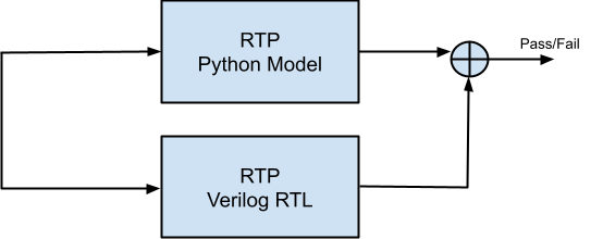
This Python implementation of RTP will be used to test actual RTL implementation of RTP as shown below
Well i thought i am on vacations but not officially i guess !!!!!
Please look at the source code here. Note that you need to have MyHDL and Dpkt libraries installed to get this code to run.
Figure 1: Write into Image Buffer by raw HDMI stream
Figure 2: Read from Image Buffer by RTP block
Here is the RTP packet of length 1086 bytes. Only the RTP payload is shown.
raw_bytes=ACE19577A2EB3665189599C2644D56420366CE5D386E802AFD79E54852C9C2AAB8C6DE15974BCEC18F7B7D3D0C8D50ED37D7808D498F4D773FF5D29278EC24BE1572F68F56BC2AF94E544148563E9493F585E2E9C3FBE7DA38D520656158D794D8F06D926B8B7B3B49B60974B7A0E1DC3496B1DAD4F110220366C35AD6217AC0EFC15FB2734DBD0D1D60B27E3FFAF13A2344BA3E8B2CF7276BFB1C94E2F86A9C503DF79F2882C948A8EE8572D7B09CE197D1F95E62285FB918009F25C41B4CA405AC51A28B3C71A6D28F450E64CD7A6DD7BB6CD48FE2035FE5BF30A16C3E67287C2BF9A1213FBE5EF98CA58BA22DA618B716AC98E4618EE450CB62CF57C0D4C626A652B9D47A539CF568641A7EBB750899DB81CBD3D09CC121ED2E48A8429FF72C214F88C028ABB2BE8FD6DFB79E36D0E8A42EA09B472AA3B82177DABD182B9938010688782C6663B9B515DEF5072A518640D7486723297E017A4C2C94F3E781E510B95BD0A74B51584AC39F477585BA4F70ED625F2D6477C5B1357D3C36EFAD68165D97AC3E1216A8E6B96EB6F2FB30562D24CEF996E1C675DEA2E5D977F3C0A1C3103ED7E2774CE69C1F136D5043CC9E4AA6E78A05D3113798AA0439C131EC4CCD509375EBC9942A67B44E8DC1DC992AEE7D56E0733716327E16831D8DE0453740C5A250B6352F4F74C411911DE4714D3ACCC6C71D4D614B68ACA6B676A97533604A491AE262D1AAC6AF55A45BEC0AEA382262F6036A8CBE0471FE3AB7AD7ACE1ED565D715E9B6CE0308FB019B7661E68FBB13512F6413AC5EC5456D83863BEEC1A53D9DDF857FC36D1EB732D07FECE2430B10FE253A60953AFCB38790899C775844F422DB83B5AB2A12443711BF46BA5C35E1C2BAD4BCC464ED59A4D924993A295006B34B63693E7B6A414D5894F91985E58AEEAAA08C430F7C354CBDCF43BD3D5458DC1856458919E001CFCA45BD12536F2B9D6855622741C58D7359C17F8AA943A147E36E634BA89E9EDD92188F3CE4E72DA2AF8D2B267248A9FCAA5C30D141DF2548FCE7531414D106AE4EEA84887984700F09C3A8D9E67B614CB7A1B417233D1D97EFC13F30011BE67EEE5CDACCD933816046E7919E2D22C568614756AE3E26323FCBE892968F2D99B655A18A4961A3C0F0DFE4FC56442071FD9516765998287E507CA9C58FDB2E8281CBF1B11942C919B36102A2B55AC9544094A6B78A931687552AC48BD9D4C0D580271A9FE19D37787959428DF04C886E38A39F2C601B9A299D70C4F6B4E82D7A02C8DD72B5F7A73596A29E13E4D6BE0F183C86E2CCDB6A95FC06AAF58754A21F6ABC3EC8237CACDCB55DE06D9651EF2E6A230E12C1BBB378B23CD785668DEEEDF06E8A2F71A0D6166B1BD281D729CDF2AC9763F0FDD390DB7025637EF68C6AD40AF1B01CB52A5BA289782B299C35550D6B5F0A4B6931F42226F455448403A77A29FA746C5CC27CFC81808E77A5DBCCC6D9BE5CB5E892A1CF2429FFC5EE8DE98BC06923B208E
byte_cnt= 1086
raw_cnt = 362
RTP header is not shown. It can be printed by calling pack_hdr( ) function on RTP object. Other functions that can be called on RTP object are
cc
csrc
data
m
p
pack
pack_hdr
pt
seq
ssrc
ts
unpack
version
x
Figure 3: Use of RTP Python Model to Verify RTP Verilog RTL
Well i thought i am on vacations but not officially i guess !!!!!
Subscribe to:
Posts (Atom)