
Figure 1: HDMI2USB at the top level
Once you have this schematic, you can click on wires and blocks to see which is connected with which.
My goal was to determine the interface of Image Buffer to RTP Packetizer (it is still under development). After spending sometime and bouncing back and forth with mentor, i was able to understand it. The interface looks like following
Figure 2 : RTP Interface with upstream Image Buffer (Red arrow shows Flow Control signals)
Here is a text and graphical snapshot of the simulation of the Image Buffer. The text shows 4 writes into the FIFO using Bus in (while reads are blocked on Bus out) and then the 4 writes are read on Bus out while blocking writes on Bus in.
#Simulation time [w=write operation] --> write address , read address | input: enable status, fifo_full status bytes value , output: enable status, fifo_full status read value
#Simulation time [r=read operation] --> read address , write address | input: enable status, fifo_full status bytes value , output: enable status, fifo_full status read value
39: [w] --> 1, 0 --> | i:e1 f0 E95B32, o:e1 f1 000000
45: [w] --> 2, 0 --> | i:e1 f0 0D2F9F, o:e1 f1 000000
51: [w] --> 3, 0 --> | i:e1 f0 6B6951, o:e1 f1 000000
57: [w] --> 4, 0 --> | i:e1 f0 549BB1, o:e1 f1 000000
63: [r] --> 0, 5 --> | i:e0 f0 549BB1, o:e1 f0 000000
69: [r] --> 1, 5 --> | i:e0 f0 549BB1, o:e1 f0 DE99C9
75: [r] --> 2, 5 --> | i:e0 f0 549BB1, o:e1 f0 E95B32
81: [r] --> 3, 5 --> | i:e0 f0 549BB1, o:e1 f0 0D2F9F
If the above looks gibberish to you, you can look at the waveform below or read the source code
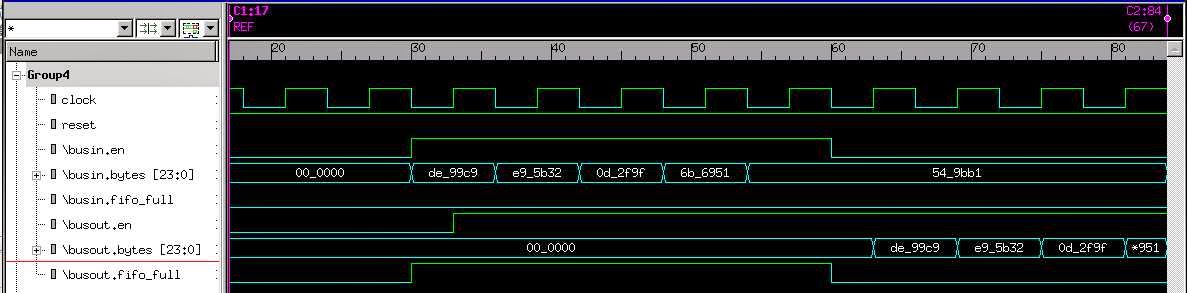
Figure 3: Waveform of FIFO WRITE and then READ operations
Also added basic RTP packet processing functionality in the source code to receive raw data from Image Buffer and turn it into RTP packets.
Couple points for other readers. One of the first tasks was to
ReplyDeletedetermine the exact interfaces required for the RTP packetizer.
That is, what is the upstream interface and the downstream
interface. For the RTP packetizer the ImageBuffer is the
upstream source and the UDP IP is the downstream sink.
In addition, a verification environment is being developed to drive
and monitor the inputs and outputs, this includes creating basic
models for different components in the hdmi2usb design. The hope
was, with a simulation environment majority of the focus could be
on the RTP packetizer design (liken to TDD)
This works, so far, has been done in Python and using MyHDL for
hardware specific modeling. Packages have been identified in
Python that can create (and verify?) RTP packets. One thought
was to use the packages, using the hardware interfaces, and create
a golden model of the RTP packetizer ... this is work in progress.